Circuit Diagrams & Programming
Accelerometer:
Acelerometer measures the acceleration in X and Y direction and gives the signals to the Arduino. Details on its purpose is described in Hardware page.
Acelerometer measures the acceleration in X and Y direction and gives the signals to the Arduino. Details on its purpose is described in Hardware page.

H-bridge:
Supply voltage was given from the 9v battery. This H-bridge runs by separate 5v from Arduino. Two H-bridges for each motor were used. Total four Arduino outputs were used. Details on its purpose is in Hardware page
Supply voltage was given from the 9v battery. This H-bridge runs by separate 5v from Arduino. Two H-bridges for each motor were used. Total four Arduino outputs were used. Details on its purpose is in Hardware page
Software design
Programming/Controller:
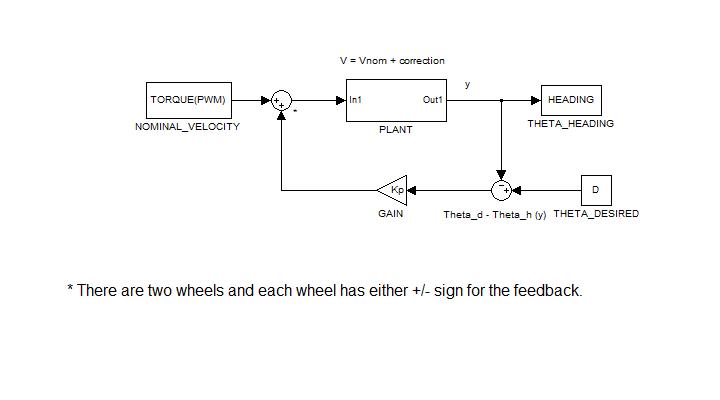
For this eraser, basic proportional controller was implemented. Please refer to the figure above. Our goal is to make the eraser go straight on the board. Hence our input is the sum of nominal velocity and +/- feedback for each wheel of the motor and output is the heading (angle or theta). Details on how this angle was calculated will be discussed in the next paragraph. Our desired theta is zero degree. We calculate the difference between the actual heading and desired theta. This difference is fed to the input, multiplied by Kp. Here, Kp is some value we found by tuning and experimenting. Hence, suppose that our eraser was going to the right and heading up. Then this controller allows it to head down by turning the top and bottom wheel to spin in the opposite direction. Their difference in speed will increase proportional to the error (desired theta - actual theta). Otherwise when the eraser runs straight, the both wheels run at the full speed in the same direction. As a note, in this program, we can change the nominal velocity, Kp, and desired theta at the beginning of the code. Because of the way it was structured, in the future, our desired theta can be changed to make the eraser make turns.
The heading as mentioned before was found using accelerometer. Since accelerometer measures acceleration, we use gravity, which always points down, as a reference point to measure the current heading of the eraser. For each position of the eraser (heading to the right, left, down, and up), serial monitor gives different values up to 512 for x and y positions each at the steady state (when the eraser is fully speed up). For each position, the average values are found for x and y again. When they were divided by the gravity to normalize and use C command "atan2" to find the angle in radians since angle is arc tangent of y over x. This gives us current position of the eraser. And surely enough, going straight to the right is at angle zero. This is also our desired theta. Hence when the eraser is heading up or down, its value is something other than zero and the difference will be fed into the controller for the next input.
The heading as mentioned before was found using accelerometer. Since accelerometer measures acceleration, we use gravity, which always points down, as a reference point to measure the current heading of the eraser. For each position of the eraser (heading to the right, left, down, and up), serial monitor gives different values up to 512 for x and y positions each at the steady state (when the eraser is fully speed up). For each position, the average values are found for x and y again. When they were divided by the gravity to normalize and use C command "atan2" to find the angle in radians since angle is arc tangent of y over x. This gives us current position of the eraser. And surely enough, going straight to the right is at angle zero. This is also our desired theta. Hence when the eraser is heading up or down, its value is something other than zero and the difference will be fed into the controller for the next input.
